Data Acquisition
»
Newsletters
Monitor - ISSN 1472-0221 Welcome to Monitor, thank you for subscribing. In spite of the rise of newer communication technologies like Ethernet and wireless protocols, RS-485 remains widely employed in numerous situations where its specific advantages are valued. Today we recap exactly what makes it still useful and explain the different RS485 set ups. You can download Monitor as a pdf file from https://www.windmill.co.uk/monitor/monitor292.pdf.
* Understanding RS485 Web link: https://www.windmill.co.uk/rs485.html RS-485 (Recommended Standard 485) is still widely used in various industries and applications. Despite being an older technology, RS-485 remains popular in numerous industrial situations due to its robustness, reliability and long-distance communication capabilities. In RS485
two wires are required for each signal. If you wish to
transmit four signals then eight wires are needed. The
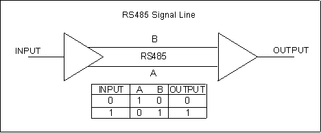
figure below shows a single RS485 signal being
transmitted. To transmit a logic 1, line B is high and
line A is low. To transmit a logic 0, line B is low and
line A is high. The advantage of this arrangement is
that signals can be transmitted faster and over greater
distances than is possible with a single wire. The RS485 standard defines only the electrical characteristics of the driver. When instruments are described as having an RS485 interface
this tells you nothing for sure about the signals being
transmitted. Usually though, only the Transmit Data (TX)
and Receive Data (RX) of a normal serial port are converted
to RS485. The other signals of the serial port are
not used. Two are commonplace:
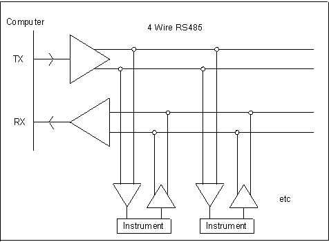
4-wire (full duplex) and 2-wire (half duplex). Full Duplex means that data can pass simultaneously
both to and from the instruments. This requires
4 wires - one pair to Transmit and one pair to
Receive. The computer alone controls the TX
transmit line. It sends out a message which includes
an Address. The addressed instrument alone replies by
driving the RX line. This does mean that all the connected instruments must
use the same software protocol - otherwise there will
be confusion as to which instrument is being addressed.
A simple conversion of RS232 to RS485 will suffice
for this arrangement and no special demands are
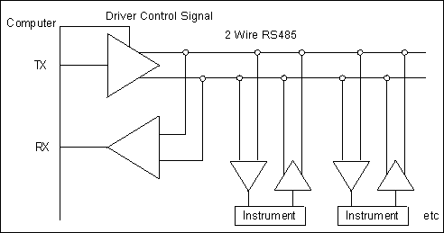
made on general purpose software such as ComDebug. Half Duplex means that data can only pass in one
direction at a time. In this arrangement both TX
and RX signals share a single pair of wires. This
can save in installation costs. The computer drives the lines to send out its
request message but must turn its driver off to
allow the instrument to reply. This is the tricky
bit. However USB-to-Serial converters can
perform the task of controlling the RS485 driver
very well. If you need to implement a 2-wire
RS485 system you should always obtain a USB-to-RS485
converter that advertises this special feature. Such a unit can work
with general purpose software such as ComDebug or
HyperTerminal. Be aware though that it may not work
with the special software supplied by instrument
manufacturers which may assume a particular RS232-
to-RS485 converter and may produce errors when
used with any other unit. When a signal is sent down a cable there is always
a reflection voltage which returns up the cable.
This reflection is bigger as signals' edges get
faster and lines get longer. It can be minimised
by terminating the ends of the line with the
characteristic impedance of the system. This is
120 ohm for RS485. Ideally an RS485 system consists of a single
linear cable (no branches) with 120 ohm resistors
connected across the 2 wires at each end of the
cable. RS485 can handle speeds of over 10 Mbits per
second and line lengths of over 1 km. If you
are operating anywhere near these values you must
arrange your wiring close to the ideal. For many applications where baud rates are slow
(say 9600 baud), and lines are only tens of meters
long, this is not essential. The wiring requirements
can then be relaxed to allow cables to run in star
arrangement from the computer and the terminating
resistors become optional. In many RS485 multidrop systems there are times
when no unit is driving the RS485 lines. They can
then go to any voltage and may produce serial errors.
To avoid this it is often necessary to fit resistors
which pull one line high and the other line low putting
the line into the passive state. The RS485 converters
usually include such resistors which can be connected
if needed. You will find that your RS485 signal names for a line
pair are either A,B or +,-. In an ideal world you would
simply connect A on the computer to A on the instrument.
However these names are not consistently applied by
manufacturers and you may need to connect A on the
computer to B on the instrument. Free RS485 Trouble-Shooting Software Question "I found your website and was looking at the Microlink 840: Versatile Data
Logging and saw it has 8 hardware inputs. Does it have serial connectors at
the back to connect with instruments? Answer The Microlink 840 is designed for logic signals, switch closures, analogue signals and digital sensors, so wouldn't be appropriate for Serial connections. However, you can use Windmill and comDebug software to talk to instruments with serial or tcp connections. This is free to our newsletter subscribers! You will need a usb-to-serial adaptor to connect your serial instruments to the computer. Contact monitor@windmillsoft.com for a free copy of Windmill and comDebug.
Learn more about the Microlink 840 data acquisition and control unit and serial communications and comDebug.
The Newsletter for Data Acquisition and Control
Issue 292 June 2023![]()
![]()
Contents
* Your DAQ Questions Answered: hardware or software to connect serial devices?Understanding RS485
RS485 - Two wires for greater distances

RS485 Wiring Arrangements
Full Duplex System: Sending and Receiving Data over 4 Wires

Half Duplex System: Sending and Receiving Data over 2 Wires

Preventing Voltage Reflection
Ideal RS485 Wiring
Line Pull Ups: Avoiding Serial Errors
RS485 Signal Names: Caution Required
RS485 Software Tools
You can use the comDebug software to pin-point and solve problems with RS485 connections.Your DAQ Questions Answered: Serial Connectors
I have a scenario where there are 4 instruments, 3 of which has serial, and
the other has Serial and TCP. I would like to know what's the best
configuration to link these 3 instruments and what products, be it hardware
or software would you recommend from Windmill.
"
Subscribe to Monitor