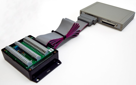
Understanding Signal Conditioning
13 March 2024
Signal conditioning is the technique of making a signal from a sensor or transducer suitable for processing by data acquisition equipment.
For example, if you were measuring a voltage signal smaller than a few millivolts, you might need to amplify it. If you had a signal contaminated with noise you could filter it.
Proper signal conditioning is essential in getting an accurate measurement of your signal. It is the first step of computerised data acquisition.
Types of Signal Conditioning
Amplification
Amplification increases a voltage signal to a level suitable for digitisation by the DAQ equipment. Typically a data acquisition device is calibrated for input voltages in the 0 to 10 V range. A small voltage, such as that coming from a thermocouple or strain gauge bridge may need to be amplified 1000 times to make it between 0 and 10 V. Our data acquisition systems have programmable amplifiers - you can simply select the amplification or range from Windmill software.
If your signal is larger than the maximum input range then you will have to divide the signal down using a resistor network.

Dividing down a 0–100 V signal to 0–10 V
Excitation
Many transducers, like strain gauges and RTDs (resistance temperature devices), need a power supply. The signal from these transducers is either a voltage or a mA current. For many transducers the supply will be low voltage DC, but for transducers based on capacitance measurement an AC supply may be required.
Our systems can be equipped with power supplies suitable for providing the excitation voltage(s) required. Because the choice of power supply will depend on the number and type of transducers, you should draw up a list of transducers and their excitation requirements. The information needed includes voltage range and current requirements, and for AC excitation voltages, the frequency used.
Excitation is commonly needed for measuring force, pressure, relative humidity, temperature, level, light level, concentration and vibration.
Linearisation
Linearisation is needed when the signals produced by a sensor don't have a straight-line relationship with the physical measurement, as is the case when using thermocouples to measure temperature. Linearisation is sometimes achieved using signal conditioning. Windmill data acquisition software, though, has built-in linearisation for B, E, J, K, N, R, S and T type thermocouples so no prior signal conditioning is needed.
Cold-Junction Compensation
Thermocouples are popular temperature sensors because they are cheap, versatile and sturdy. They consist of two dissimilar metals joined together, making a continuous circuit. If one junction has a different temperature to the other, an electromotive force (voltage) is set up. This voltage varies with the temperature difference between the junctions. If the temperature at one junction is known, the temperature at the other junction can be calculated.
The system depends on knowing the temperature of one of the thermocouple junctions - the cold junction. Housing this junction in an isothermal box keeps the temperature constant, and a cold junction sensor in the box tells the system the temperature. Windmill systems automatically compensate for the cold-junction temperature in software.

An open cold-junction measuring box connected to data acquisition hardware
Filtering
Filtering reduces noise errors in the signal. For most applications a low-pass filter is used. This allows through the lower frequency components but attenuates the higher frequencies. The cut-off frequency must be compatible with the frequencies present in the actual signal (as opposed to possible contamination by noise) and the sampling rate used for the A-D conversion.
A low-pass filter that's used to prevent higher frequencies, in either the signal or noise, from introducing distortion into the digitised signal is known as an anti-aliasing filter. These generally have a sharper cut-off than the normal low-pass filter used to condition a signal. Anti-aliasing filters are specified according to the sampling rate of the system and there must be one filter per input signal. They are commonly used when measuring, for example, vibration.
You can use Windmill software to enable and disable filters in the data acquisition hardware.
Isolation
A high transient voltage at one input may damage not only the input circuit, but an also propagate to other equipment connected to that input. You can prevent this type of damage by providing isolation between inputs.
High Impedance
Certain types of transducer have a very high output impedance and are not able to supply enough current to use a normal voltage input. When connected to a normal amplifier, the currents drawn from the transducer can seriously distort the input signal. Typically glass electrodes used to measure pH, or gas concentration probes, are of this type. You should connect them to a voltage measuring circuit with a very high input impedance.
Rms Signal Conditioning
You can monitor signals from electrical power supplies when the current signal is sensed with a current-sensing resistor, and high voltage signals are divided down using resistive dividers. Software scaling functions in Windmill turn your low-voltage readings back to the original power supply voltage and current values.
Since many power supplies provide an AC signal, a signal conditioning input which provides a DC signal proportional to the root mean square (rms) amplitude of the input signal would be suitable.